Preventing Cable Heat Buildup in High-Power PoE Networks
High-power PoE has become a core enabling technology for modern networks, supplying power to devices such as Wi-Fi 6/7 access points, PTZ cameras, LED lighting, building sensors, and PoE-powered workstations that rely on central servers rather than local computers. By delivering power and data over a single cable, these devices can be supported from a centralized low-voltage infrastructure.
As power levels increase with UPOE and PoE++ (IEEE 802.3bt), the choice of copper cabling has a direct impact on both performance and safety. When multiple high-power PoE connections are installed in the same cable bundle, electrical resistance and ambient temperature can cause heat build-up inside the cable jacket. Managing this heat is essential to maintaining data performance, protecting cable materials, and ensuring devices receive stable voltage across the full channel length.

Why High-Power PoE Heats Up Cables
High‑power PoE systems deliver up to 90–100 W at the PSE, which translates into higher DC current flowing through each conductor pair. As current increases, resistive heating in the copper conductors rises, and that heat has less opportunity to dissipate when cables are tightly bundled or placed in enclosed pathways.
Three main factors determine how much the cable temperature rises under PoE load:
Conductor size and DC resistance (smaller gauge = more heat)
Bundle size and installation method (tightly packed bundles trap heat)
- Ambient temperature and pathway (ceilings, conduits, and outdoor spaces can run hot)If heat is not controlled, insertion loss increases, which can reduce the usable channel length and impair data performance, even though power delivery itself may still appear to work.
Understanding Cable Heating Tables
Industry guidance documents such as TIA TSB‑184‑A and ISO/IEC TR 29125 provide cable heating tables that show the expected temperature rise for different categories, gauges, bundle sizes, and PoE power levels. These tables are used by designers and installers to verify that the total temperature (ambient plus heat rise) does not exceed the cable’s rated operating temperature.
In practice, cable heating tables help to:
- Determine safe maximum bundle sizes for PoE++ applications
- Decide when to de‑rate cable lengths or reduce power levels in hot environments
- Select higher‑performance cabling (such as Cat.6A with 23 AWG conductors) to minimise heat rise in dense bundles
- By applying these tables during the design phase, organisations can avoid conditions where high‑power PoE causes premature ageing of the cable jacket or pushes channels out of standards‑compliant performance.

WHY CATEGORY 6A
is recommended for UPOE/PoE++
Category 6A has emerged as the recommended baseline for new installations that intend to support UPOE and PoE++ at scale. Compared with lower categories, Cat.6A typically offers larger 23 AWG conductors, lower DC resistance, and better thermal behaviour under load.
Key reasons Cat.6A is preferred for high‑power PoE include:
Reduced conductor resistance: Larger copper cross‑section means less power is lost as heat and more is delivered to the device.
Lower temperature rise in bundles: Cat.6A exhibits smaller heat increase for the same PoE current compared with Cat.5e or Cat.6, especially in high‑count bundles.
Improved headroom: Even with added insertion loss from elevated temperatures, Cat.6A retains sufficient performance margin for 10GBASE‑T and multi‑gigabit applications.
For environments such as smart buildings, digital ceilings, and high‑density wireless deployments, Cat.6A provides both the electrical and thermal characteristics required to support multiple generations of PoE‑driven devices.
Cable Construction Features That Limit Heat Buildup
Beyond category and gauge, cable construction plays an important role in how effectively heat is managed in high‑power PoE installations. Choices around shielding, separators, and jacket materials can all influence temperature rise and long‑term reliability.
Important construction characteristics for high‑power PoE cabling include:
Solid copper conductors rather than CCA, ensuring predictable resistance and safe heating behaviour
Thermally robust jacket and insulation compounds rated to at least 60 °C, and often 75 °C or 90 °C for demanding environments
Shielded or foil‑wrapped designs in high‑density or constrained spaces to assist with heat dissipation and electromagnetic performance
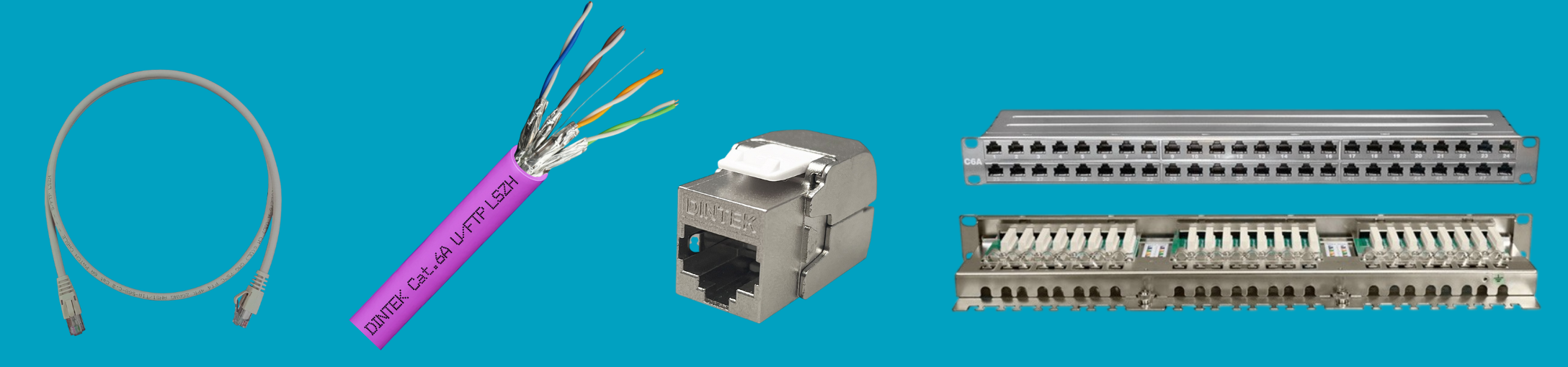
DINTEK PowerMAX+: Designed for High-Power PoE
DINTEK’s PowerMAX+ copper cabling solutions are engineered to support modern high-power PoE applications, including UPOE and PoE++ deployments where multiple powered devices are installed within dense cable bundles. Built using high-quality copper conductors and carefully selected insulation materials, PowerMAX+ cables are designed to meet or exceed relevant international standards for both performance and safety.
Within the PowerMAX+ portfolio, Category 6A solutions are optimised to deliver reliable high-power PoE across the full 100-metre channel while controlling temperature rise in bundled installations. Stable insertion loss performance is maintained even under elevated thermal conditions, making PowerMAX Cat.6A particularly well suited to digital building infrastructure, converged IP systems, and future-ready wireless backhaul environments.
DINTEK PowerMAX+: Compliance and Standards Alignment
PowerMAX+ cabling is designed and rigorously tested to align with the latest structured cabling and PoE-related standards, giving network designers confidence that installed systems will operate safely and predictably within defined limits. This includes compliance with Category 6A performance requirements, as well as industry guidance covering remote powering and thermal behaviour in cable bundles.
When deployed as a complete DINTEK channel, incorporating matched connectivity, patch cords, and patch panels, PowerMAX provides verified support for high-power PoE while maintaining standards-compliant performance across the full rated temperature range. The system also delivers the electrical headroom required for multi-gigabit and 10GBASE-T applications. As a result, organisations specifying DINTEK PowerMAX for new builds or network upgrades can deploy high-power PoE at scale with confidence in long-term safety, performance, and reliability.


