Twisted Pair Cable Certification Testing for Ethernet Networks
In modern enterprise networks, the structured cabling system is the critical foundation that supports all data transmission. Unlike visible components such as switches and servers, the cabling infrastructure is often hidden in walls, ceilings, and floors — yet it is expected to perform flawlessly for 10 to 20 years or more.
As applications evolve from 1 Gigabit Ethernet to 10 Gigabit Ethernet and soon to 25G and 40G in certain environments, the demands on twisted pair cabling have increased dramatically.
Simply terminating and installing cable is no longer sufficient. International standards such as ANSI/TIA-568.2-D, ISO/IEC 11801, and EN 50173 require that installations be verified through field certification testing. This process confirms that the cabling not only functions at present but is capable of supporting future high-speed applications with margin to spare.
Certification testers such as the Fluke DSX-8000 provide a pass/fail result, but the real value lies in understanding the detailed test parameters reported. These parameters — including attenuation, crosstalk, return loss, and others — tell the story of how the cable behaves electrically. By learning how to interpret them, installers and project owners gain the ability to verify workmanship quality, diagnose installation issues, and assure customers of long-term network reliability.
This article explores the six most critical parameters measured during Cat 6A certification testing, explains why they matter, and concludes with why choosing DINTEK cabling solutions consistently delivers superior results.

Cable Length
Definition: The total electrical length of the cabling link as measured by the tester using Time Domain Reflectometry (TDR).
Importance: Standards specify maximum lengths: 90 m for the permanent link and 100 m for the channel (including patch cords). Exceeding these distances increases attenuation and reduces the available bandwidth for error-free transmission.
A PASS on length ensures compliance with TIA/ISO distance rules. Large discrepancies between measured and installed lengths may indicate coiled cable hidden in ceilings or poor routing practices. Certification testers typically measure length per pair — differences between pairs may highlight manufacturing defects or cable damage.
Attenuation
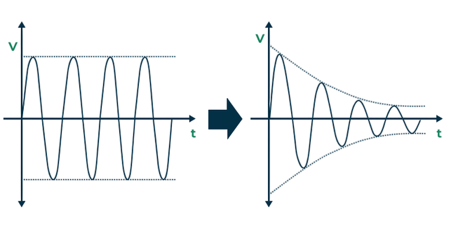
Definition: The gradual loss of signal strength as it travels along the cable, expressed in decibels (dB).
Why it Matters: Higher attenuation means the receiving equipment gets a weaker signal, increasing error probability. Attenuation increases with frequency (higher data rates) and with length. For Cat 6A, limits are specified up to 500 MHz, the bandwidth required for 10GBASE-T operation.
Good Results Look Like: Attenuation values comfortably below the TIA limits. Low attenuation margins are critical in environments with higher ambient temperatures, since copper resistance (and hence signal loss) rises with heat.
Excessive attenuation is often caused by overly long runs, excessive patch cord length, or poor conductor quality.
NEXT (Near-End Crosstalk)
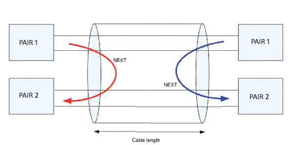
Definition: Interference caused when the signal on one pair induces noise onto an adjacent pair, measured at the transmitting end.
Why it Matters: Crosstalk is the most common source of transmission errors in twisted pair cabling. With 10GBASE-T using all four pairs simultaneously in full-duplex, even small amounts of crosstalk can destabilize communication.
Interpretation: NEXT is expressed in decibels. Higher values are better, as they indicate stronger isolation between pairs. Failures are often linked to poor termination techniques — e.g., untwisting pairs too far, sloppy punch-downs, or sub-standard connectors.
When repeated NEXT failures occur, always inspect patch panel terminations and outlet connections before replacing cable.
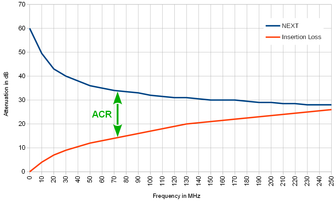
ACR-N (Attenuation-to-Crosstalk Ratio, Near-End)
Definition: The difference between NEXT and attenuation. ACR-N = NEXT – Attenuation
Why it Matters:
- ACR-N represents the usable signal-to-noise ratio at the near end.
- Even if NEXT is high, if attenuation is also high, the resulting ACR-N margin may be small.
- Positive margins indicate the signal is stronger than the noise, ensuring reliable transmission.
Good ACR-N results confirm both low loss and strong pair isolation. Poor results require examining both cable quality and termination workmanship.
ACR-F (Far-End Crosstalk, ELFEXT)
Definition: Crosstalk measured at the far end of the cable, adjusted for attenuation.
Why it Matters:
- Ensures that noise induced by distant transmitters does not degrade long-distance performance.
- Particularly relevant for 10 Gigabit Ethernet, where signals traverse the entire bandwidth simultaneously.
- Like ACR-N, a positive ACR-F margin indicates the desired signal is stronger than the unwanted noise.
- Failures may be due to poor pair balance or external interference in high-density cable bundles.
Return Loss
Definition: A measure of reflections caused by impedance mismatches along the cabling link.
Why it Matters:
- Any discontinuity, such as a kink, poor connector, or inconsistent conductor geometry, creates reflections.
- Reflected signals interfere with forward transmission, causing bit errors.
- 10GBASE-T, which uses sophisticated echo cancellation, is especially sensitive to poor return loss.
Higher return loss values across the frequency range.
Failures often point to poorly terminated connectors, damaged cable, or the use of incompatible patch cords.

Putting It All Together
Each parameter is important on its own, but their true value comes from how they interact:
- Attenuation ensures the signal remains strong enough.
- NEXT and ACR-N guarantee pair-to-pair isolation.
- ACR-F ensures long-distance stability.
- Return Loss confirms uniformity of the link.
- Length ensures compliance with design standards.
When all of these are within standards, the cabling system is certified to reliably support applications up to 10 Gigabit Ethernet over 100 meters — the cornerstone of modern enterprise networks.
Why DINTEK Products Deliver Reliable Certification Results
Choosing the right cabling manufacturer directly affects certification outcomes. DINTEK Electronic Limited designs its copper and fiber solutions with strict adherence to ANSI/TIA and ISO/IEC standards, and goes further by implementing additional quality controls and third-party verifications.
Superior Conductor Quality
Certification Confidence
Advanced Shielding Options
Precision Pair Balancing
Consistent Impedence
Peace of Mind
Conclusion
Certification testing transforms cabling from a hidden risk into a proven asset. By understanding parameters such as attenuation, NEXT, ACR, and return loss, installers can interpret more than just a PASS/FAIL result — they can demonstrate quality, diagnose issues, and guarantee long-term reliability.
DINTEK cabling solutions, with their superior engineering and third-party verified performance, make certification easier, more predictable, and more reliable. For contractors, this means fewer call-backs. For customers, it means a network foundation built to last.


